
Page 37 - Softbound_Edition_19_en
P. 37
Solenoids Solenoids
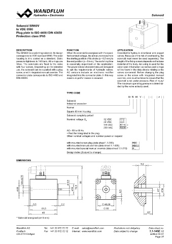
Solenoid
CHARACTERISTICS DC AC Solenoid SIN60V
Static pressure tightness 350 bar (seal diameter of valve Totale stroke (mm) 5,5 5,5 to VDE 0580
max. 25 mm) Working stroke (mm) 2,5 2,5 Plug plate to ISO 4400 / DIN 43650
With seal diameter of valve = 26 mm: Nominal power (W) 30
Static pressure tightness = 315 bar (VA) 35 Protection class IP65
Coil winding insulation class H Armature weight (kg) 0,044 0,044
Connection / Power supply Over device plug connection to Solenoid weight (kg) 0,76 0,76
ISO 4400 / DIN 43650, (2P+E), Voltage range (VDC) 10-250
other connections on request (VAC) 40-250*
Protection class to EN 60 529 IP65 DESCRIPTION fuNCTION APPLICATION
Relative duty factor 100 % The SIN60V is a switching solenoid. Its design When the solenoid is energised with the speci- Essential for hydraulic directional and poppet
Reference temperature 50 °C ∗ For AC voltages below 40 VAC DC solenoids plus rectifier plugs corresponds to VDE standard 0580. The steel fied nominal voltage, the armature moves from valves. Because of the risk of overheating, the
Seal Viton, other on request are available. housing is zinc coated as a standard. Static the starting position of its stroke (s = 8,5 mm) to solenoid must never be used separately. The
21 VDC to 24 VAC
Fluid Mineral oil, other fluid on request pressure tightness is 160 bars. All o-rings are the end position (s = 0 mm). The switching time lenght of the fixing screws depends on the base
Switching cycles 15 000/h 32 VDC to 36 VAC Viton. The solenoids are fixed to the valve is essentially dependent on the application. material of the body. An o-ring is used for the
Mounting screws 4 x M5 (Quality 8.8) with four screws. Depending on the intended The power-stroke characteristics are designed valve seal. Information on screws and o-rings
Housing Zinc coated steel housing, other 12VDC 24VDC 115VAC 230VAC use, the solenoid can be supplied with a plug to suit the requirements of hydraulic valves. will be found in the data sheets relating to the
surface treatments on request. Nominal resistance (Ω) 5 21,8 445 1'400 screw, or with integrated manual override. The AC versions include an electronic rectifier valves concerned. Before changing the plug
Number of windings (-) 770 1’560 7’000 13’000 connector plate corresponds to ISO 4400 and integrated into the connector plate. In this way screw or the screw with integrated manual
maximum perfor-mance is assured.
DIN 43650.
override, care must be taken to ensure that the
Inductivity (mH) 19 82 solenoid is not under pressure. Risk of injury!
The maximum operating pressure is determin-
ded by the valve actually used.
TyPE CODE
SI N 60 V - - #
Solenoid
PERfORMANCE ACCESSOIRES Industrial execution
F = f (s) Force-stroke characteristics Normal
Plug HB0 ∗ Article No. 239.2033
F [N] Plug with integrated manual override HB6 ∗ Article No. 253.8001 Square 60 mm housing
160 K0062 ∗ acc. data sheet 1.1-300 Solenoid completly potted
Nominal voltage U 12 VDC G12
N
140 Special manual override see data sheet 1.1-310 24 VDC G24
115 VAC R115 ∗
Plug grey Article No. 219.2001 230 VAC R230 ∗
120 Plug black Article No. 219.2002 AC= 50 to 60 Hz
∗ Rectifier integrated in the plug
Rectifier plug grey Article No. 219.2105
100 Other nominal voltages and nominal power on request
Rectifier plug black Article No. 219.2106
80 with mounted screw plug (data sheet 1.1-300) HB0
with mounted manual override (data sheet 1.1-300) HB8,5
with mounted special manual override (data sheet 1.1-310) H...
60
1 Design-Index (Subject to change)
40
2 DIMENSIONS
20 9,2
0
0 1 2 3 4 5 s [mm]
8 x0,75
M 4,9 99
20 32 70,5 7 14
6,5
1: U = 100 % U Reference temperature = 20 °C (30W)
N
2: U = 90 % U Reference temperature = 50 °C
N
Solenoid in operating temperature (19W)
The values refer to U = 24 VDC. 0,3 2,2 48,08
N
With other nominal voltages deviations can occur.
For curve 2 the solenoid has been mounted on a body 46 x 64. 81,5 60
85 10*
* Solenoid energised (s= 0 mm)
Technical explanation see data sheet 1.1-400
Wandfluh AG Tel. +41 33 672 72 72 E-mail: sales@wandfluh.com Illustrations not obligatory Data sheet no. Wandfluh AG Tel. +41 33 672 72 72 E-mail: sales@wandfluh.com Illustrations not obligatory Data sheet no.
Postfach Fax +41 33 672 72 12 Internet: www.wandfluh.com Data subject to change 1.1-125E 2/2 Postfach Fax +41 33 672 72 12 Internet: www.wandfluh.com Data subject to change 1.1-145E 1/2
CH-3714 Frutigen Edition 06 20 CH-3714 Frutigen Edition 05 01
Page 37